Saturday 27 October 2012

Mark's now got a 1959 C15!

As usual, click any image to zoom in.

Mike & Annie Kilvert came round this morning to drop Mark's bike off and came in for a couple of hours for a brew and a chat!


After they'd left to visit friends in the local area, Mark and I set off to BSA Lightning Spares to see Brian for a few new parts (silencer, gear lever rubber, kickstart rubber, handlebar rubbers) before setting off on an odyssey. Didn't get home 'til dark!


Mark seems to have got the hang of a kickstart after years on Japanese bikes - turns out a bit of throttle while kickstarting means your knee doesn't get rubbed raw like this...

Sunday 7 October 2012

Speedo calibrated!

Mark has been pressuring me to get the speedo sorted out before he rides it again, and quite right too. In fact, he is always right - he makes me sick.
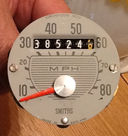
I reassembled the speedo today after first drilling an access hole in the rear of the speedo casing and then temporarily sat the speedo in the headlamp. I connected the speedo cable and set off to duel with the local radar device.  After the third time of adjusting the magnet plate distancing screw I approached the radar device and it displayed in large green numbers 30 mph.

Went back for a rerun to prove it wasn't a fluke and again it displayed 30 mph. I went back and rode the bike at 31 mph according to the speedometer and as I approached the radar detector  31 mph flashed up on the device. Really chuffed! Rode back home and secured the speedometer in the headlamp. I managed to tap the metal that Smiths had originally "punched" to stop the screw from turning, and secured the screw in place. This was achieved through the new drill hole.

As a final test I rode the bike to the opposite end of town and rode the bike through the other radar speed detector and lo and behold riding the bike at 
 31 mph the detector confirmed that the speedo is now accurate.

I tested it at 31 instead of 30 mph because the margin for error is less than the thick line of 30mph on my speedometer would show, if that makes sense.

Next on the list is: 
1.  Clean air filter
2.  Make a transparent cover to view internals of the Float Chamber.

Apart from glass, which I assume would be difficult to drill, I need something that is not attacked by petrol that would be easy to buy locally.

Friday 5 October 2012

Speedo's

As usual, click any image to zoom in. 

No, not my budgie smugglers but the speedometer.


The speedo reads several MPH too fast. The upside is I won't get caught speeding but the downside is the odometer is advancing too quickly.


I've managed to get the speedometer bezel off and I have removed the internal mechanism.


I have repainted the red pointer. The brass adjusting screw was locked in place by the metal surrounding it having been "punched" to prevent movement. I have gleaned that by adjusting the screw the metal plate next to the rotating magnet moves either nearer or away from the magnet. If the plate is nearer to the magnet the speed shows faster than actual and the opposite applies.


I will drill a hole in the rear of the case to allow adjustment of the screw without having to remove the mechanism every time it needs tweaking.


I'll use the speed radar near my house to calibrate the speedo, as well as getting someone in a car to double-check the accuracy.


Thursday 4 October 2012

Running rich?

As usual, click any image to zoom in. 

Took the bike for a run last night and the bulbs lasted fine and no misfire - bonzer!

It feels like it is running rich though: a combination of a lack of grunt and a poor tickover that needs "tickling" of the throttle to keep it going at times.


I removed the air-filter to inspect thinking that if it was blocked it would be like having the choke "on" with all the obvious consequences. 


The active filtering area is outwards from the central rivet to about 2" diameter (up to the 2nd raised ring, from the centre). There is a circular piece of black cloth fitted between the black mesh and rear metal plate.  The filtered air is sucked through a circular rubber tube, of the same diameter, which then feeds the carburettor input.  The area outside of the 2nd ring is non-effective as it butts up against the inside of the battery compartment.


The reverse metal side of the filter shows a darkened area showing where the air has passed through in the past.  Holding the filter up to the light seems to suggest things are not that well with the airflow.  I am not suggesting this is the entire problem but it should help in weakening the mixture.

I'll try cleaning the filter in fuel and see what happens.

Tuesday 2 October 2012

New rectifier and ignition coil


As usual, click any image to zoom in. 


Apart from the bad earths I fixed recently, last night I found that the wire coming off the positive terminal (earth) decided to become loose in its circular spade connector.  Unbelievable! That alone would cause bulbs to blow and the engine would possibly misfire. While the cable was intermittently disconnecting over bumps etc, the full AC output of the alternator would be going through the bulbs and also possibly damaging the ignition coil.

Today I decided to fit a new rectifier even though original one measured fine, but was starting to become loose on its central stud.


I then tried running the bike with the new rectifier installed and with lights on main beam.  Even though the rectifier can handle up to 35 Amps peak it was getting pretty hot.  A heat sink was obviously required. One was duly cut to shape and before being bolted in place some heat sink compound was applied to assist in the cooling process. 


Initial tests seem to confirm that the fault that was causing the bulbs to blow might have also damaged the ignition coil. With a new coil fitted the bike did not manifest the same misfiring and cutting out fault that was apparent when the old coil was still in situ.  We'll know for sure when the bike is taken for a good run.  


Watch this space.